Introduction Unpacking SPIN Quick Start Front Panel Rear Panel Set-Up Using SPIN Preset List MIDI Features Specifications Warranty
Spin is a fully MIDI implemented, specialized sound processor in a half-rack package. It accurately duplicates the effect of a rotating speaker cabinet "miked" with four microphones (stereo upper and stereo lower).
SPIN's rotating speaker effect is a double rotor type simulation. There is an 800 Hz frequency crossover which routes the input signal's high-frequency components to a three delay rotor simulation and the low-frequency components to an identical three delay rotor simulation. The two stereo sets of rotor signals are recombined and sent to the audio outputs. S pin's three delays per rotor makes for a "fat" and realistic simulated rotating speaker sound. Front panel controlled overdrive provides highly authentic tube-like distortion which is important for this type of sound.
Spin has a low-level high-impedance guitar input. The rotating speaker effect is not only a favorite of organists, but also guitarists and studio producers.
Spin is easy to use. 15 presets run the gamut of rotating speaker effects. Virtually every usable rotating speaker setup is represented. Some of the presets included are the "Memphis" sound in which the lower drum's slow motor is unplugged, various mike placements, and various speed compliments.
Foot-switch inputs are provided for both Brake and Fast / Slow rotor control. Another useful feature is the ability of using MIDI aftertouch to toggle the rotors' speeds. MIDI continuous controllers can be used to tweak rotor speeds and accelerations.
Inside SPIN's package you will find:
Please return the warranty card soon after your purchase. The information you provide will allow Voce to keep you informed about updates and new products.
I want to...
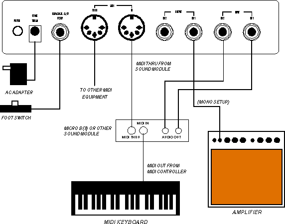
Refer to the diagram above for setting up SPIN.
Connect the audio inputs
To connect a pick-up type musical instrument to SPIN (i.e. guitar) a convenient low-level high-impedance input is provided on the front panel. This jack accepts a 1/4" tip/sleeve type plug.
Connect line-level inputs (i.e. mixer or keyboard) to the rear panel audio input connectors. These inputs are mixed to mono internally and are provided as a convenience for when only a stereo input signal is available.
Adjust the input gain so that PK (peak) LED indicator is yellow during the loudest passages of play. A green indication is for levels which are too low and a red indication is for levels which are too high. This adjustment procedure is used for both the GUITAR and line-level inputs.
Connect audio outputs to amplifier/mixer
SPIN provides two stereo audio outputs. These outputs contain a stereo image which represents a 4 microphone simulation (2 microphones spaced about 100 degrees apart pointed at the upper rotor and a similar setup for the lower rotor).
For the original SPIN:
Both CH1 and CH2 outputs should be connected for stereo operation to suitable audio system (i.e. digital piano audio inputs, stereo mixer / sound system line level inputs). If mono audio operation is desired, connect the instrument amplifier (mixer etc.) to CH1.
The CH2 output is a stereo (tip/ring/sleeve) type 1/4" connector. The ring connection is for channel 1's output. You may use this connection in lieu of connecting to the CH1 output.
For the SPIN II pedal:
SPIN II has a single stereo TRS output for which you use only one side for mono. In other words, don't mix the left and right to make mono.
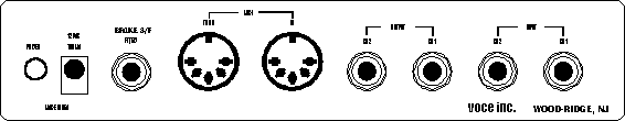
MIDI IN Input
To use the MIDI control features of SPIN, the MIDI output of a controller or sequencer must be connected to SPIN's MIDI IN. This allows the MIDI controller to change SPIN's presets, change rotor speeds, and tweak rotor parameters. See MIDI Features section.
MIDI THRU Output
Useful in connecting more than one MIDI module in a daisy chain configuration. Use this output for sending a "carbon copy" of the MIDI data appearing at the MIDI IN connector to other MIDI devices.
PEDAL
A momentary foot pedal (such as a sustain pedal) may be connected to this input to toggle the rotating speaker effect between a slow or fast state. The front panel S/F LED indicator will toggle on or off when the foot-switch is operated. If control of the brake function is also required, a stereo plug may be used for this input, the ring and sleeve connections control the brake function while the tip and sleeve connections control the S/F function.
AC Adaptor
SPIN requires an external AC adaptor. Make sure that you first connect the small barrel connector on the rear panel of SPIN before connecting the AC adaptor to the wall outlet.
Select the Basic MIDI Channel
Set the basic MIDI channel on the MIDI channel selector located on the front panel of SPIN. The basic MIDI channel should be the same as the channel that your MIDI controller uses to transmit MIDI program and control change information to SPIN. If MIDI Omni Mode is selected, SPIN will respond to all MIDI channels.
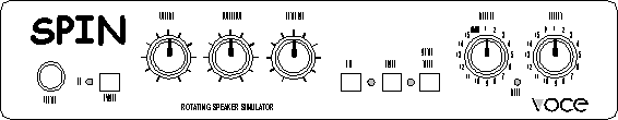
After hooking up SPIN as explained in the Set-Up section, you will be ready to start enjoying SPIN's rich rotating speaker sound. SPIN was designed to be very easy and intuitive to use. The following is a brief description of SPIN's controls together with an explanation of their usage.
Volume: Adjust the VOLUME (input gain) so that PK (peak) LED indicator is yellow during the loudest played passages. A green indication is for levels which are too low and a red indication is for levels which are too high. This adjustment procedure is used for both the GUITAR and line-level (rear panel) inputs.
Bypass: To disable the rotating speaker effect produced by SPIN, press the BYPASS button so that it is in the "in" position. The VOLUME control will still control the signal gain but no rotating speaker effect will be heard. When SPIN is in bypass mode, a monophonic output signal is produced. This is because the stereo inputs are permanently mixed to a monophonic signal as required by SPIN's rotating speaker effect. The BYPASS control is useful for hearing the difference between the effect produced by SPIN and the "straight" sound.
Overdrive: Overdrive may be used to simulate the sound of an amplifier driven into clipping. It realistically simulates the organ sound used by many "R & B" and rock bands or the sound of an overdriven guitar amplifier.
To adjust the amount of overdrive, gradually turn the Overdrive knob clockwise and listen to the changes in the applied sound. Notice how the amount of overdrive increases as you turn the knob. Adjust to taste.
Rotor Bal (balance): SPIN's rotating speaker effect is a double rotor type simulation. There is an 800 Hz frequency crossover which routes the input signal's high-frequency components to a three delay rotor simulation and the low-frequency components to an identical three delay rotor simulation. The two stereo sets of rotor signals are recombined and sent to the audio outputs. The balance between the amount of signal going to the upper rotor (high-frequencies) and the amount of signal going to the lower rotor (low-frequencies) can be controlled by the ROTOR BAL knob. Turning the Rotor Bal knob clockwise increases upper rotor output level and decreases lower rotor output level.
S/F push-button: The rotating speaker effect is simulated by having a horn rotor and drum rotor speed up or slow down at different rates. Rotor speed can be set to either slow or fast by pressing the front panel button, using a foot-switch, using MIDI Aftertouch, or by MIDI control number 68.
The rotating speaker rotor speeds are indicated by the state of the S/F LED. When the LED is lit, the rotors speed up with independent accelerations to the fast rate. When the LED is turned off, the rotors slow down with independent decelerations to the slow rate. Select between the two rotor speeds by pressing the S/F push-button.
BRAKE push-button: Allows the rotating speaker effect's rotors' to slow down to a complete stop. The BRAKE LED lit indicates that the simulation is in brake mode. Brake mode takes precedence over any other rotation mode (fast or slow). When brake mode is turned-off (LED off), the simulation's rotors speed up to either the slow or fast speeds depending on the state of the S/F LED.
AFTERTOUCH push-button: SPIN's S/F (slow/fast) function can also be controlled by MIDI aftertouch (both polyphonic key pressure and channel pressure). When the AFTERTOUCH push-button is in the "in" position, applying pressure to a MIDI keyboard which supports aftertouch will toggle the S/F (slow/fast) function. This allows control over the S/F (slow/fast) function without having to press a button or step on a foot-switch.
Presets: SPIN comes with 15 preset rotating speaker setups. These presets control various parameters of the rotating speaker effect like: rotor acceleration, slow speed, fast speed, microphone placement, and EQ. Any of these preset setups can be accessed instantly via MIDI by placing the preset selector on the P position and sending the desired program change from your MIDI controller. The P position tells SPIN that all program changes will now be set by your MIDI controller. See the next page for a list of SPIN's presets.
| Preset # | Description |
| 1 | Model 122 MP - 2 rotors / middle pulleys / mic close |
| 2 | Model 122 SP - 2 rotors / small pulleys / mic close |
| 3 | Model 122 LP - 2 rotors / large pulleys / mic close |
| 4 | Foam Drum - 2 rotors / middle pulleys / mic close |
| 5 | Model 120 - foam drum only / mic close |
| 6 | Steppenwolf - drum only / loose belts / mic close |
| 7 | Memphis - drum slow motor unplugged / mic close |
| 8 | Joey - both slow motors unplugged / mic close |
| 9 | Model 122 Wide - 2 rotors / middle pulleys / wide stereo |
| 10 | Model 122 Mono - 2 rotors / middle pulleys / mono compressed |
| 11 | Guitar Phaser - medium rate / very close mic |
| 12 | Guitar Phaser - fast rate / very close mic |
| 13 | Guitar Phaser - fast rate / mono compressed |
| 14 | Watery Guitar - fast rate / close mic |
| 15 | EQ'd Watery Guitar - fast rate / med. slow rate / close mic |
Note that the last five presets are optimized for use on guitar.
Several parameters can be modified by MIDI continuous controller messages: rotor fast speed, rotor slow speed, rotor acceleration, and the microphone placement for both the upper and lower rotors. See the following MIDI Features section for more information.
SPIN allows control of several of its effect parameters via MIDI control changes. The following table lists the functions and parameters that can be controlled by MIDI, their MIDI control numbers, and their associated control values:
| Effect | MIDI Control # | Value |
| Volume | 7 | 0 = softest, 127 = loudest |
| Rotating Speaker Slow/Fast | 68 | 0 - 63 = Slow, 64+ = Fast |
| Rotating Speaker Brake | 74 | 0 - 63 = Off, 64+ = On |
| Upper Rotor Slow Speed | 86 | 0 = slowest, 127 = fastest |
| Upper Rotor Fast Speed | 88 | 0 = slowest, 127 = fastest |
| Upper Rotor Acceleration Time | 87 | 0 = shortest, 127 = longest |
| Upper Rotor Mic. Distance | 85 | 0 = closest, 127 = farthest |
| Lower Rotor Slow Speed | 76 | 0 = slowest, 127 = fastest |
| Lower Rotor Fast Speed | 78 | 0 = slowest, 127 = fastest |
| Lower Rotor Acceleration Time | 77 | 0 = shortest, 127 = longest |
| Lower Rotor Mic. Distance | 75 | 0 = closest, 127 = farthest |
Note the MIDI control numbers are fixed, therefore to control the functions mentioned in the table you will need a programmable MIDI controller. The various buttons, wheels, sliders, or pedals of your MIDI controller must be assigned to the control number corresponding to the function you wish to control.Because of the wide variety of MIDI controllers (keyboards, computers, or sequencers) available on the market today, you will have to determine which MIDI controller is appropriate for this particular application. For example, you may elect to use the MOD wheel on your MIDI keyboard to control the S/F (slow/fast) rate or you may wish to use the MOD wheel on your MIDI keyboard to adjust the fast speed of the upper rotor.
Examples:
1. Controlling the S/F (slow/fast) speed via a MOD wheel:
Program the MIDI keyboard's MOD wheel to send data for MIDI control number 68 instead of control number 1. Since the MOD wheel is a continuous controller, it will output a control value of 0 through 127 depending on what position it is set to. To select the FAST rate simply flip the MOD wheel all the way up (on most keyboards up means away from you) or all the way down (towards you) for the SLOW rate. The rotating speaker simulation will begin changing speed after the MOD wheel crosses the midway point (when the control value switches between 63 and 64).
2. Using a continuous controller to adjust the rotor's fast speed:
Determine which controller you'd like to use to set the upper rotor's fast speed. Let's use the MOD wheel for this example. Program the MIDI keyboard's MOD wheel to send data for MIDI control number 90 instead of control number 1.
Since the MOD wheel is a continuous controller, it will output a control value of 0 through 127 depending on what position it is set to. Set SPIN's rotor speed to fast (S/F LED on). You'll notice now that the upper rotor's speed will track the position of the MOD wheel. Rotating the MOD wheel away from you will set the rotor speed quite high, moving it closer to you will set the speed to a slow rate. This function is handy for customizing the rotating speaker effect to suit your taste. It also allows for real-time control of the rotor speeds which can be used in place of the built-in acceleration / deceleration function.